1

I am having trouble gaining an intuition about UML Use Case Diagrams and what to include in them and what not, starting from a given scenario in prose.

I have read through my course materials and the according chapters in "Software Engineering (Sommerville)" and "Use Case Modelling (Bittner)".

However, I still struggle modelling this particular scenario:

The electronic payment mechanism of a petrol station is to be completely automated. The customer puts his credit card into a card reader. The credit card is examined by communication with the bank and a maximum quantity that the customer is permitted to pump is returned from the bank. If the credit card is invalid, refuelling is refused and the credit card is returned. Otherwise, the customer is permitted to remove the hose from the mounting plate and to start refueling. The refueling is terminated either when the maximal permissible amount of petrol is dispensed, or when the customer decides to put the hose back into the mounting plate. The amount owed for the petrol dispensed is charged to the customer’s credit card account when the refueling process has finished. After completion of the transaction the credit card is returned.

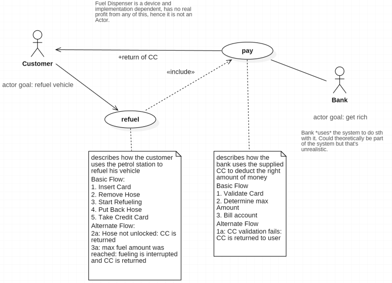
After doing some reading, I came up with the following diagram:

enter image description here

unboxed texts in gray show my reasoning.

  • Is this correct? Am I missing something?
  • Is the association from Pay to Customer reasonable?
  • I am particularly unsure if there should not also be Use Cases like Remove Hose and Put Back Hose. Some say, Use Cases should show the steps that the user has to do in order to achieve his goal. Others say, that each use case should provide a meaningful profit to the user. Are refuel and pay really the only two sensible use cases here?

1 Answer 1

2

Your scenario describes only a single use case:

Use case: Refuel car
Primary/initiating actor: Customer
Secondary/supporting actors: Bank
Basic flow:
1. Customer inserts card
2. Bank validates card and determines limit
3. Hose is unlocked
4. Customer is informed of which hose to use
5. Customer takes hose
6. Customer refuels car
7. Customer puts back hose
8. Charge card for amount owed
9. Return card
Alternative flows:
2a. If card invalid
2a.1. Inform customer 2a.2. Go to step 9.
6a. Maximum amount reached while dispensing fuel
6a.1. Block flow of fuel
6a.2. Wait until customer replaces hose, then continue with normal flow

Use case diagram in PlantUML

4
  • Thanks. What is your reasoning that you do not use the Bank as an actor?
    – ngmir
    Commented Apr 6, 2018 at 8:18
  • @ngmir: I am using the Bank as an actor. A single use-case can have interactions with multiple actors, as long as there is only one that starts the use-case. Typically, the Bank is a passive actor that only responds to interactions that are initiated by the system you are modelling. Commented Apr 6, 2018 at 9:08
  • @ngmir Use case diagrams are like a Table of Contents entry for the text of a use case -- they're useful when you have lots of use cases and you want to see an overview. In this sense, the diagram lacks much detail. This answer doesn't show the diagram, but it would be very simple (one oval with the use case name) and a line to the Customer and Bank as actors. Commented Apr 8, 2018 at 0:38
  • @ngmir I suggested an edit with the following diagram: planttext.com/plantuml/img/… Commented Apr 8, 2018 at 0:48

Your Answer

By clicking “Post Your Answer”, you agree to our terms of service and acknowledge you have read our privacy policy.

Not the answer you're looking for? Browse other questions tagged or ask your own question.